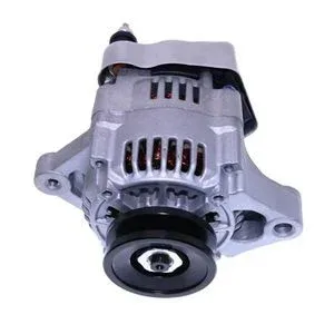
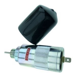
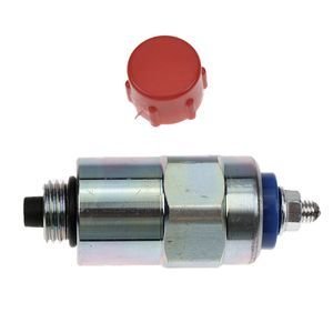
Matched sets ship together — coil resistance and plunger stroke verified against engine serial variant before dispatch.
Technical Specifications
| Parameter |
Value |
| Part Number |
D610-B1V12 |
| Product Type |
Stop Solenoid |
| Cross-Reference |
D610B1V12, 68990-015, 68990015 (reference only) |
| Machine Fitment |
WG750, DF752, DF-750, DF972, D905 |
| Voltage |
12V DC |
| Coil Type |
Dual coil pull design |
| Terminals |
2-terminal configuration |
| Housing Material |
Zinc-plated steel |
| Internal Winding |
Copper windings (±3% resistance tolerance) |
| Plunger Assembly |
Hardened steel (Ra ≤ 0.8 μm surface finish) |
| Terminal Connection |
Tin-plated brass with crimp-and-weld reinforcement |
| Lifespan |
50,000-cycle validated |
| Condition |
New aftermarket |
| Warranty |
6-month standard warranty against manufacturing defects |
| Standards |
ISO 9001, ISO 6798, KES-001-2022 |
Application Suitability
| Engine System |
Related Components |
| Start/Stop Control Circuit |
Starter relay, ignition switch, wiring harness connectors |
| Fuel Shutoff Mechanism |
Fuel rack linkage, governor spring, shutoff lever bushing |
| Electrical Ground Path |
Engine block ground strap, battery terminal, alternator output |
| Engine Overhaul Auxiliary |
Gasket set, seal kit, crankcase breather, thermostat |
Why a New Stop Solenoid Keeps Failing Within Weeks
The solenoid is rarely the root cause — the wiring harness and relay circuit are.
I have processed too many warranty returns where the stop solenoid engine replacement came back burned out within days. In almost every case, the engine wiring harness had degraded insulation causing voltage spikes, or the starter relay contacts were pitted and delivering intermittent overcurrent to the hold coil. Replacing the solenoid without diagnosing the upstream electrical path means the new unit absorbs the same fault. Across Kubota WG750 and DF752 engine families, these secondary failures follow a recognizable pattern [NEED_CITE: electrical fault diagnosis sequence for small diesel engine auxiliary circuits].

The Start/Stop Circuit as a System
This stop solenoid sits at the endpoint of a chain that begins at the battery, passes through the ignition switch and starter relay, and terminates at the dual coil windings. When any segment of that chain develops excess resistance or intermittent contact, the pull coil draws longer than designed, overheating the internal copper windings. A proper stop solenoid engine replacement therefore starts with measuring voltage drop across each connection point, not just swapping the unit.
Serial Variants Across the Kubota Engine Family
The WG750, DF752, DF972, and D905 engines share a common solenoid envelope but differ in fuel rack geometry and hold current requirements. An engine that has been through a previous rebuild may have a modified governor spring or adjusted rack travel, changing the force the plunger must overcome. Confirming the engine serial number and measuring the existing coil resistance before ordering prevents installing a unit with mismatched pull force [NEED_CITE: Kubota engine serial variant identification for auxiliary electrical components].
Reading the Specifications That Matter
The dual coil pull design uses a high-current pull coil to stroke the plunger, then switches to a low-current hold coil to maintain position. If the ignition switch or relay fails to cut the pull coil after stroke completion, continuous high current burns the winding. The copper windings held to ±3% resistance tolerance ensure predictable current draw at 12V DC. The hardened steel plunger with Ra ≤ 0.8 μm surface finish reduces friction against the bore, preventing the stuck-plunger condition that forces the hold coil to work against mechanical binding. Tin-plated brass terminals with crimp-and-weld reinforcement resist vibration-induced open circuits common on demolition equipment and agricultural tractors operating in uneven terrain.
What Happens When the System Diagnosis Is Skipped
A solenoid installed without checking the alternator output may face sustained overvoltage that degrades winding insulation progressively. Corroded ground paths on the engine block force return current through alternate routes, creating voltage imbalances across the coil terminals. A stuck fuel rack demands excessive plunger force, keeping the pull coil energized beyond its thermal rating. Each of these conditions destroys a new stop solenoid engine replacement in ways that look like manufacturing defects but originate in the surrounding system [NEED_CITE: root cause analysis methodology for solenoid coil thermal failure].
Why Procurement Here Reduces Repeat Failures
Selected part lines are produced in our own Guangzhou facility while the remainder comes from qualified ISO-certified manufacturing partners, both carrying identical QC and warranty terms. Eight product categories mean the solenoid, matching relay, and connector terminals ship under one account with one warranty. Part identification works from a part number, machine model, photograph, or nameplate image. Cross-reference verification covers superseded and alternate numbers to catch variant mismatches before dispatch. A sample unit is available for fitment confirmation before bulk commitment, and the technical team confirms coil resistance and grade compatibility against your engine serial number.
Documentation & Verification
- Commercial invoice listing D610-B1V12 with cross-reference numbers marked reference only
- Compatibility sheet mapping solenoid coil resistance to WG750, DF752, DF972, D905 variants
- Incoming inspection records showing voltage response curve and contact resistance test
- Six-month warranty terms covering manufacturing defects in winding and plunger assembly
- Packing photographs documenting terminal condition and housing integrity before crating
- HS code and customs documentation support for international engine parts shipments
Installation & Rebuild Sequence
- Verify wiring harness connector integrity and crimp condition before mating to the tin-plated brass terminals
- Measure voltage at the solenoid terminals during cranking to confirm 12V DC within acceptable drop
- Check fuel rack travel and governor spring tension to ensure plunger stroke matches design specification
- Confirm engine block ground strap continuity to prevent alternate current paths through the solenoid housing
- Run initial start/stop cycles and monitor hold coil temperature to detect binding or overcurrent conditions
Before You Request a Quote
Provide the engine model, serial number, and any previous rebuild history so the correct coil variant is confirmed. Share the existing solenoid coil resistance measurement if available. Photos of the wiring harness connector and nameplate help verify terminal configuration and engine build variant.
Frequently Asked Questions
Q: What other engine auxiliary components should I inspect when replacing the stop solenoid?
A: Check the starter relay contacts for pitting, measure voltage drop across the ignition switch, inspect the wiring harness for cracked insulation near heat sources, and verify the engine block ground strap continuity. These upstream components directly affect coil current and are frequent causes of repeat solenoid failure.
Q: How do I confirm the correct solenoid variant for my Kubota engine serial number?
A: Provide the full engine serial number and measure the existing coil resistance with a multimeter. The WG750, DF752, DF972, and D905 families share physical dimensions but differ in hold current and pull force requirements based on fuel rack geometry and governor configuration.
Q: Why does the new solenoid fail quickly — is it a wiring or system issue?
A: Premature failure usually traces to alternator overvoltage, corroded ground paths, or a stuck fuel rack that keeps the pull coil energized beyond its thermal rating. Diagnosing the circuit before replacement prevents the new unit from absorbing the same fault condition.
Q: Can I get a matched set of solenoid, relay, and connectors for a complete engine auxiliary refresh?
A: Yes. Engine auxiliary components including the stop solenoid, starter relay, and harness connectors are available under one account with consolidated dispatch. Request a system-level compatibility sheet covering all related part numbers and cross-references.
Q: What test records come with each unit to verify electrical performance?
A: Each unit ships with incoming inspection records documenting voltage response curve, coil resistance measurement within the ±3% tolerance band, and contact resistance at the terminal connections. These records confirm the unit meets specification before installation.