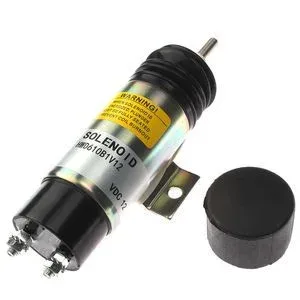
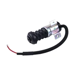
Engine Sequence Variants Confirmed — Every D610-B1V12 stop solenoid ships only after the engine serial prefix is matched to the correct terminal and bracket configuration, preventing field fitment rework on Kubota platforms.
Technical Specifications
| Parameter |
Value |
| Part Number |
D610-B1V12 |
| Product Type |
Stop Solenoid |
| Cross-Reference |
D610B1V12, 68990-015, 68990015 (reference only) |
| Machine Fitment |
Kubota WG750, DF752, DF-750, DF972, D905 |
| Electrical Specification |
12V DC, dual coil (pull-in + hold-in) |
| Terminal Configuration |
2-terminal |
| IP Rating |
IP54 |
| Condition |
New Aftermarket |
| Warranty |
6 months against manufacturing defects |
| Quality Standard |
ISO 9001 |
Application Suitability
| Engine System |
Related Components |
| Start / Shutdown Control Circuit |
Wiring harness, relay, ignition switch contacts |
| Fuel Shutoff Linkage |
Fuel rack, governor spring, shutoff lever pivot |
| Engine Overhaul Electrical Check |
Starter motor contacts, battery cables, alternator output |
| Preventive Maintenance Inspection |
Coil resistance test, terminal corrosion check, bracket torque |
When a Stop Solenoid Fails Again Within Weeks
The root cause almost always sits upstream in the wiring or fuel shutoff linkage, not in the solenoid itself.
In Yangtze Delta workshops, I have watched mechanics replace this stop solenoid on a Kubota DF752 only to see it burn out again before the machine left the bay. The new unit draws full pull-in current because the hold-in coil circuit has a voltage drop across corroded terminals or an undersized wire run. The engine rebuild replacement for a stop solenoid becomes a cycle of repeat visits until someone traces the entire start-to-shutdown sequence. Diagnosing the fault that killed the original unit before installing the next one is the only path to a lasting repair [NEED_CITE: electrical fault diagnosis sequence for diesel engine shutdown circuits].

The Shutdown Circuit Inside the Kubota Engine System
This stop solenoid sits at the junction of the electrical and fuel systems in Kubota WG750 and DF752 engines. When the operator turns the key off, the hold-in coil de-energizes and the spring-loaded plunger moves the fuel rack to the no-fuel position. A stop solenoid engine rebuild replacement must account for how the governor spring tension and fuel rack travel interact with the plunger stroke, because an out-of-adjustment linkage will force the coil to work against higher resistance and overheat prematurely.
Engine Serial Variants That Change the Physical Fit
Kubota produced the DF752 and D905 across multiple serial prefix ranges, and the bracket hole pattern, plunger length, and terminal orientation differ between early and late production runs. I once saw a DF-750 solenoid bolt on correctly but leave a gap between the plunger tip and the fuel rack tab, so the engine would not shut down. Confirming the serial prefix against the cross-reference table eliminates that risk [NEED_CITE: Kubota engine serial prefix variant identification guide].
What the Dual Coil Architecture Actually Does
The pull-in coil delivers a high-current pulse to overcome spring pressure and move the plunger the full stroke distance. Once the plunger seats, the hold-in coil maintains position at a lower current draw. This two-stage design keeps continuous power consumption manageable and prevents the coil from overheating during extended engine runs. If the wiring harness delivers the pull-in voltage but cannot sustain the hold-in current due to resistance in aged connectors, the plunger chatters and the coil eventually fails. Understanding this sequence is essential when performing a stop solenoid engine rebuild replacement.
Reading the Specs That Matter in the Field
The 12V DC rating means the coil is designed for standard mobile equipment electrical systems, but actual voltage at the terminal can drop significantly on machines with long wire runs or undersized harnesses. The IP54 rating protects against dust ingress and splashing water, which covers most compact excavator and agricultural tractor environments but not high-pressure washdown. Dimensional tolerance of ±0.15 mm governs the plunger-to-bracket relationship, so even small amounts of corrosion or debris on the mounting face can shift the plunger alignment enough to cause binding [NEED_CITE: IP rating definitions for mobile hydraulic and electrical components].
The Cost of Skipping Root-Cause Diagnosis
Replacing the stop solenoid without checking the wiring harness, relay, and ignition switch contacts turns a single-component swap into a recurring failure loop. The machine returns to the workshop, the technician pulls the unit again, and the customer loses confidence in the part rather than the diagnosis. On fleet machines with frequent restart cycles, each repeat visit multiplies labor cost and equipment downtime far beyond the price of a thorough electrical inspection done the first time [NEED_CITE: repeat failure patterns in engine shutdown electrical systems].
What This Supply Chain Brings to the Bench
Own production lines and qualified sourced supply carry the same QC and warranty terms, so the D610-B1V12 you receive has passed identical functional testing regardless of which facility built it. Eight product categories mean the wiring connectors, relays, and seal kits that accompany this solenoid ship in one consignment under one account. The minimum order is one piece, which matters when a single machine is down and you need to validate fitment before committing to a fleet quantity. Part identification works from a part number, machine model, photograph, or nameplate image, and the technical team verifies engine serial variants before dispatch. Cross-reference verification covers superseded and alternate numbers to catch listing errors before they reach your workbench.
Documentation & Verification
- Commercial invoice listing D610-B1V12 with engine model and serial prefix noted
- Cross-reference sheet mapping D610B1V12 and 68990-015 equivalents (reference only)
- Functional test record at 12V showing pull-in and hold-in coil current draw
- Six-month warranty terms covering manufacturing defects with claims procedure
- Packing photographs showing terminal protection and bracket condition before crate closure
- HS code and customs documentation prepared for international shipment
Installation & Rebuild Sequence
- Verify fuel rack moves freely by hand before mounting the new stop solenoid
- Clean bracket mounting face to bare metal so dimensional tolerance is not compromised by debris
- Confirm terminal orientation matches the engine wiring harness plug before tightening fasteners
- Measure voltage at the solenoid terminal during pull-in to detect upstream wiring resistance
- Cycle the ignition off and on several times after installation to confirm clean shutoff response
- Inspect starter motor contacts and battery cable condition as part of the same electrical system check
Requesting a Fitment-Confirmed Quote
Send the Kubota engine model, serial prefix from the nameplate, and any available photograph of the failed solenoid including the bracket and terminal layout. If the nameplate is worn, a clear image of the engine block casting number allows the technical team to narrow the serial range. For fleet orders, note whether any units have undergone previous rebuilds that may have changed the governor spring or fuel rack configuration.
Frequently Asked Questions
Q: How do I confirm this solenoid matches my specific Kubota engine serial variant?
A: Provide the full engine serial number from the nameplate or block casting. The technical team cross-references the serial prefix against bracket hole pattern, plunger length, and terminal orientation records to confirm the D610-B1V12 variant matches your engine build. This step prevents fitment gaps or linkage misalignment that occur when early and late production variants are swapped.
Q: What upstream faults cause repeated solenoid failure after replacement?
A: Corroded wiring harness connectors, undersized wire gauge, failing relay contacts, and worn ignition switch internals all create voltage drop that starves the hold-in coil. The pull-in coil fires but cannot sustain the plunger, causing chatter and overheating. Tracing voltage at the solenoid terminal during operation reveals these faults before the replacement unit is destroyed.
Q: Does the dual coil design require different wiring from a single coil solenoid?
A: The D610-B1V12 uses a two-terminal configuration where the wiring harness manages pull-in and hold-in stages internally through a relay or controller. The external connection is the same two-wire setup, but the harness must deliver adequate current for both stages. Verify the harness specification matches the dual coil requirement before installation.
Q: Can I order a sample to validate fitment before committing to a fleet quantity?
A: Yes, single-piece orders are standard. Mount the sample on one machine, confirm bracket alignment, plunger engagement with the fuel rack, and clean shutoff response across multiple cycles. Once fitment and electrical performance are verified, proceed with the fleet quantity knowing the serial variant match is correct.
Q: What other engine electrical components should be inspected when replacing this solenoid?
A: Check the starter motor contacts for pitting, test battery cable resistance end to end, inspect the ignition switch for internal wear, and verify relay operation. These components form the complete start-to-shutdown circuit. A fault in any one of them can create the voltage condition that caused the original stop solenoid to fail.