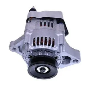
Engine Sequence Verified — Carrier CT2-29TV and CT3-44TV serial variants mapped to correct alternator excitation output before dispatch.
Technical Specifications
| Parameter |
Value |
| Part Number |
30-00423-00 |
| Product Type |
Alternator |
| Cross-Reference |
30-00423-00, 300042300, 30-00409-64, 300040964, 30-00363-00, 300036300, 30-01114-06, 300111406, 30-01151-00, LS17139, 4702601, A1737B, 4702610, 4702611, 4702603, 93105 (reference only) |
| Machine Fitment |
CT2-29TV, CT3-44TV, CT3/69TV, Genesis R70, Genesis R90, TM800, TM900, Maxima 1000, Maxima 1200, Maxima 1200 MT, Maxima 1300, Maxima 1300 MT, Maxima 1550, ULTRA XL, XTC, XT, Ultima XTC, X2 1800, X2 2100, X2 2100A, X2 2100R, X2 2500A, X2 2500R |
| Voltage |
12V |
| Minimum Continuous Output |
110A |
| Ripple Voltage |
< 200 mV RMS |
| Diode Junction Temperature Rating |
150°C |
| Shaft Runout |
≤0.03 mm per ISO 21940-11 |
| Rotor Winding Tolerance |
±0.5% |
| Housing Material |
Die-cast aluminum with electroplated steel mounting flanges |
| Condition |
New Aftermarket |
| Warranty |
3–12 months against manufacturing defects |
| MOQ |
1 piece |
| Standards |
ISO 9001, ISO 21940-11, SAE J1171 |
Application Suitability
| Engine System |
Related Components |
| Charging system on Carrier CT2 and CT3 diesel engines |
Voltage regulator, serpentine belt, belt tensioner, crankshaft pulley |
| Auxiliary electrical supply for X2 series transport refrigeration units |
Battery cables, fuse links, electrical harness connectors |
| Cold-start recovery circuit on Genesis R70/R90 and Maxima reefers |
Starter motor, glow plug relay, battery isolation switch |
| Continuous-duty charging on TM800/TM900 and ULTRA XL units |
Alternator cooling fan, mounting bracket hardware, drive pulley alignment tool |
Why Replacing the Alternator Alone Fails Within One Service Cycle
A 12V Alternator for Carrier CT2 CT3 engine rebuild only resolves the symptom when the charging circuit root cause goes unexamined.
Early in my career sourcing for a refrigerated fleet, I ordered an alternator matching the book number for a Carrier X2 2100 unit. The part arrived, bolted in, and passed initial voltage checks. Three weeks later the same unit came back on the hook with a dead battery and burned diode pack. The belt tensioner had been slowly failing, throwing harmonic vibration into the alternator shaft at every cold start. Nobody had checked it because the work order only said "replace alternator." [NEED_CITE: vibration-induced bearing failure in engine-driven alternators]
That experience shifted how I approach every auxiliary electrical component quote. An alternator does not fail in isolation — it fails because something upstream in the belt drive, pulley alignment, or voltage regulation circuit placed abnormal load on its bearings or diode bridge. When a workshop requests a replacement, I now ask what diagnostics were performed on the adjacent system before the old unit was pulled. This 12V Alternator for Carrier CT2 CT3 engine rebuild is designed to replace worn charging components, but lasting performance depends on addressing why the previous unit failed.

Charging System Position Within the Carrier Auxiliary Electrical Network
The alternator sits at the center of a loop that includes the battery, voltage regulator, belt drive assembly, and the electrical loads imposed by the refrigeration control module. On Carrier CT2-29TV and CT3-44TV power units, the alternator must sustain continuous output against the compressor clutch cycling and evaporator fan motors running in enclosed, poorly ventilated compartments. This 12V Alternator for Carrier CT2 CT3 engine rebuild delivers the minimum continuous amperage required to keep that loop stable without overheating the diode bridge under sustained reefer load.
Engine Serial Variants That Change Alternator Requirements
Carrier CT2 and CT3 engine families share a base architecture, but serial variants within each family carry different excitation specifications and pulley ratios. A CT3-44TV may demand a different voltage regulator pairing than a CT2-29TV, even though both accept the same physical alternator housing. When I receive an inquiry without an engine serial number, I hold the shipment until that detail is confirmed. The cost of a wrong-variant installation — a second teardown, a second round of freight, and another day of machine downtime — far exceeds the time spent verifying the build sheet. [NEED_CITE: Carrier transport refrigeration engine serial variant documentation]
Electrical Output and Thermal Endurance Under Reefer Operating Conditions
The diode junction temperature rating of 150°C directly addresses the thermal environment inside a transport refrigeration engine enclosure. Reefers operate in ambient temperatures that can exceed typical underhood readings, and the insulated compartment traps heat around the alternator housing. Die-cast aluminum construction with electroplated steel mounting flanges dissipates heat while maintaining dimensional stability through thermal cycling. Shaft runout held to ≤0.03 mm per ISO 21940-11 ensures the rotor spins true against the rebuilt engine's crankshaft pulley, preventing the harmonic vibration that accelerates bearing wear during the critical break-in period after overhaul. Rotor winding tolerance of ±0.5% keeps output stable across the full RPM range the engine sees from idle at a delivery stop to governed speed on the highway. Ripple voltage below 200 mV RMS protects sensitive control boards in modern Carrier X2 and Maxima units from electrical noise that causes erratic compressor cycling.
The Repeat Failure Pattern When Root Cause Is Ignored
Installing a new alternator on a carrier engine without inspecting the belt tensioner, pulley alignment, and wiring harness is the most common path to a repeat failure within weeks. The new unit absorbs the same vibration and electrical overload that destroyed its predecessor, and the repair cycle begins again. I have seen fleet maintenance teams go through multiple units before tracing the fault back to a worn tensioner bearing or a corroded ground cable. [NEED_CITE: electrical grounding integrity in commercial vehicle charging systems] Sourcing a replacement 12V Alternator for Carrier CT2 CT3 engine rebuild without simultaneously refreshing the belt drive and verifying circuit integrity means accepting that the machine will likely return to the bench before its next scheduled service.
Sourcing With System-Level Verification
Our selected production lines and qualified sourcing partners operate under identical quality control and warranty terms, so this alternator carries the same coverage regardless of which facility built it. The eight product categories we stock — including engine parts, electrical components, seal kits, and diagnostic tools — mean the belt, tensioner, and harness connectors ship in the same consignment as the alternator. Minimum order is one piece, so an emergency single-unit replacement does not force you into buying stock you do not need. Our Guangzhou warehouse maintains inventory on fast-failure auxiliary components for same-day dispatch on common Carrier configurations. Part identification works from the OEM reference number, machine model, photograph of the nameplate, or a description of the pulley configuration. Cross-reference verification covers superseded and alternate numbers so that older fleet units with legacy part markings are matched correctly. Sample supply is available for fitment confirmation before you commit to bulk quantities.
Documentation & Verification
- Commercial invoice listing alternator part number, Carrier engine model fitment, and shipment quantity
- Cross-reference sheet mapping 30-00423-00 and alternate numbers as interchange reference only
- Quality inspection record with full-load voltage regulation and ripple test results
- Warranty terms covering manufacturing defects for 3–12 months from delivery
- Packing photographs showing alternator protection and box labeling before dispatch
- HS code and customs documentation prepared for international reefer parts import
Installation & Rebuild Sequence
- Verify belt drive, tensioner, and crankshaft pulley condition before alternator mounting
- Clean mounting flange surfaces and inspect bolt holes for thread damage from prior overhauls
- Torque mounting hardware to Carrier specification and confirm pulley alignment with straightedge
- Check voltage regulator output and battery cable integrity before first engine start
- Run engine through warm-up cycle and log alternator output at idle and governed RPM
Request a System-Matched Quotation
Provide your Carrier engine model, serial number, and any known rebuild history so we can confirm the correct alternator variant and associated auxiliary components. If the original nameplate is worn or painted over, send a photograph of the mounting configuration and pulley setup for identification. We will return a fitment-verified recommendation covering the alternator and any adjacent parts your repair scope requires.
Frequently Asked Questions
Q: What other engine auxiliary components should be replaced together with the alternator during a rebuild?
A: The serpentine belt, belt tensioner assembly, and crankshaft pulley should all be inspected and typically replaced during a charging system refresh. On Carrier CT2 and CT3 engines, worn tensioner bearings transfer harmonic vibration directly into the alternator shaft, causing premature bearing and diode failure. Replacing these components as a matched set prevents the new alternator from inheriting the same destructive load pattern.
Q: How do CT2-29TV and CT3-44TV engine serial variants affect alternator specification requirements?
A: Different serial variants within the Carrier CT2 and CT3 families may carry distinct excitation specifications and pulley ratios despite sharing the same alternator housing dimensions. Ordering without confirming the exact engine serial risks receiving a unit whose voltage output profile does not match the regulator pairing on your engine build, leading to undercharging or overvoltage conditions.
Q: What root-cause faults in the charging system should be diagnosed before installing a replacement alternator?
A: Belt tensioner condition, pulley alignment, ground cable integrity, and voltage regulator function should all be verified before the new alternator is energized. Corroded connections and failing tensioners are the most frequent causes of repeat alternator failure on Carrier reefer engines. Addressing these faults during installation ensures the replacement unit reaches its intended service life.
Q: Does the overhaul kit for this engine include the alternator, or is it sourced separately?
A: Engine overhaul kits for Carrier CT2 and CT3 power units typically cover internal rotating and sealing components but do not include auxiliary electrical items such as the alternator. The alternator is sourced as a separate line item within the engine auxiliary components category, allowing you to specify the correct variant for your engine serial without paying for bundled items you may not need.
Q: How do I confirm the correct alternator when the original nameplate is unreadable?
A: Send a photograph of the alternator mounting flange pattern, pulley configuration, and electrical connector type. We cross-reference these physical features against Carrier engine build documentation and the OEM interchange reference to identify the correct unit. Machine model alone is often sufficient, but engine serial number provides the most precise variant confirmation.